Aluminum Nitride Contour-Mode Vibrating RF MEMS
Abstract — This paper reports on a new class of piezoelectric Aluminun Nitride contour-mode vibrating RF MEMS that have demonstrated low motional resistance, high quality factors and multiple frequencies of operation on the same silicon substrate. These resonators have been arranged in electrically or mechanically coupled arrays to form low-loss band pass filters particularly fit for IF bands used in commercial wireless handsets. In addition, very low phase noise oscillator has been demonstrated using a contour-mode micromechanical resonator in a standard Pierce design. This novel technology could revolutionize wireless communication systems by allowing the cofabrication of multiple frequency filters (IF and RF) and frequency reference elements on the same chip, therefore reducing form factors and manufacturing costs. Index Terms — Bandpass Filters, MEMS resonators, Piezoelectric resonators, Aluminum Nitride.
I. INTRODUCTION
As the demand for ubiquitous connectivity grows, the expectations of wireless appliances' functionality and interchangeability are becoming more and more exacting. RF MEMS is an emerging technology that promises to enable both new paradigms in RF systems as well as unprecedented levels of performance and integration. The principal drivers of research in RF MEMS technology are resonator-based circuits, namely filters and oscillators. Solutions capable of integrating multi-band and multi-standard devices that consume low power and have small form factors will accomplish the vision of next-generation, ubiquitous wireless communications.
Several research groups [1-4] have demonstrated individual or coupled electrostatically-driven microresonators. Although characterized by sheer high Q amenable for the implementation of frequency reference elements, these microdevices suffer from large motional resistance, Rx. For filters, a large Rx translates into the need for extremely bulky coupling elements and makes these resonators unintegrable with existing 50 Ω systems. More recent research activities have shown that dielectric transduction [5] can be employed to reduce the motional resistance of these devices. Although very promising, this technology is still unproven and suffers from some drawbacks such as intrinsically large capacitance values (due to the ultra-thin and high-K dielectric) and small electromechanical coupling coefficients which limit their use to narrow bandwidth filtering applications. Piezoelectric materials such as aluminum nitride or quartz offer larger electromechanical coupling coefficients that reduce the motional resistance of the resonators to few ohms and make them more amenable to the implementation of wide bandwidth filters. Piezoelectric resonators such as FBARs [6, 7] and shear-mode quartz resonators [8], have been successfully demonstrated and electrically cascaded to form band pass filters in the GHz range. Because film thickness sets the center frequency of these resonators, FBARs and shearmode quartz resonators complicate the manufacturing of a single-chip RF module that has multiple-frequency selective filters and frequency reference elements on the same substrate. In this work, a multi-frequency platform that can readily be interfaced with existing 50 Ω systems and standard oscillator circuitry is presented. The pathway towards an Aluminum Nitride single-chip RF front-end solution is demonstrated [9- 13]: contour-mode bulk acoustic wave resonators are fabricated on the same substrate covering frequencies of specific interest for cell phone manufacturers. A novel integrated solution that offers IF and RF filtering functions combined with a stable frequency reference element is presented. High quality factors in air, ranging from 2,000 to 4,000, were demonstrated on the same substrate for IF rectangular and ring shaped contour mode resonators. These contour-mode MEMS resonators were either electrically or mechanically coupled to form band pass filters in the frequency range between 40 and 230 MHz. Very low insertion losses ranging from 2 to 8 dB, high out-of-band rejection and the ability to interface to 50 Ω systems were demonstrated. In addition, a low phase noise (less than - 110 dBc/Hz at 10 kHz offset) oscillator was realized using a 224 MHz ring resonator in a standard Pierce design.

Figure 1: Schematic represenations of the building blocks for the filters and their mode shapes: (a) circular ring AlN resonator excited in a radial-extensional contour mode shape; (b) rectangular plate AlN resonator excited in a width-extensional contour-mode.
II. CONTOUR-MODE PIEZOELECTRIC RESONATORS
Contour-mode rectangular plate [10] and ring-shaped [11] AlN resonators are the building blocks for the band pass filters and oscillator of this work. Figure 1 shows a schematic representation of ring-shaped and rectangular plate resonators (with their mode shapes). The resonator body is made out of AlN sandwiched between bottom Pt and top Al electrodes. By applying a harmonic electric field across the film thickness, the active AlN piezoelectric layer undergoes (through the d31 piezoelectric coefficient) an in-plane lateral displacement that is greatly amplified at resonance. The center frequency of the induced bulk acoustic radial or longitudinal standing wave is determined by the lateral dimensions (primarily by the width of the ring and the plate) of the microdevice and therefore multiple frequencies can be defined on the same wafer during the lithography step. This is the main disruptive feature of this technology, which differentiate from FBAR technology and permits the realization of multiple-frequency platforms.

Figure 2: (a) SEM of eight electrically coupled ring resonators to form a ladder band pass filter at 236 MHz; (b) SEM of eight electrically coupled rectangular plate resonators forming a ladder band pass filter at 93 MHz.
It is important to state that, although FBAR resonators have been demonstrated in manufacturing environments, tight tolerances are demanded for the electrodes and AlN film thicknesses in order to target the desired frequency of vibration. In comparison, the center frequency of the microdevice is less sensitive (approximately 10x less) to the thickness dimensions of the structure for the contour-mode technology. Tolerances for the lateral dimensions of the contour-mode devices are similar to those for the film thickness of FBAR technology, but state-of-the-art IC manufacturing tools excel at defining small features lithographically, therefore reducing the challenge of accurate frequency setting. Ultimately, the realization of high frequency and accurate contour-mode structures could results in a more economically viable solution than existing FBAR resonators.
III. CONTOUR-MODE MEMS FILTERS
Contour-mode piezoelectric MEMS resonators were arranged either in electrically or mechanically coupled arrays to form band pass IF filters.
A. Electrically Coupled MEMS Filters Eight rings, all with an inner radius of 90 μm and width of 20 μm, were electrically cascaded in a ladder topology (Fig. 2a).

Figure 3: S21 response of a 236 MHz ladder filter made out of 8 ring resonators.
The frequency of the series and shunt branches were lithographically shifted by approximately 0.3%. It is important to note that a wider bandwidth (up to 2-2.5%) could theoretically be obtained, but was limited by additional parasitic capacitance introduced by the fabrication process. This filter shows moderate insertion losses of 7.9 dB (Fig. 3) at 236.2 MHz, an out-of-band rejection of 26 dB and a 20 Db shape factor of 2.79. This filter does not suffer from any other spurious resonance. The non-ideal shape factor is likely the result of slight mismatches in frequency between adjacent resonators.

Figure 4: Transmission plot for a 93 MHz ladder filter made out of 8
rectangular plate resonators.
In addition, eight 200 μm long and 50 μm wide rectangular plates (Fig. 2b) were tested in a ladder configuration. Again the frequencies were lithographically shifted by about 0.3%. An example of the electrical response of eight rectangular resonators is shown in Figure 4. In this case insertion losses as low as 4 dB were recorded at 93.2 MHz and out-of-band rejection of 27 dB were achieved. For this filter a second band pass function exists at approximately 22 MHz due to the length-extensional mode shape present in the plate.
B. Mechanically Coupled MEMS Filters The previously described filters based on electrically cascaded L-networks of AlN contour mode MEMS resonators achieve fractional bandwidths that are limited to approximately 2% by fundamental material properties. The following new class of mechanically coupled AlN contour mode filters is not subject to the aforementioned bandwidth limitation [13].
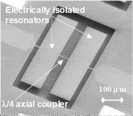
Figure 5: Two mechanically coupled plate resonators with a single quarter-wavelength long coupling bar.

Figure 6: Array of 24 contour mode plate resonator filters with mechanical series connections for multi-pole bandpass response and electrical parallel connections for reduced insertion losses.
The use of quarter wavelength long length-extensional bar coupling elements between adjacent width-extensional mode plate resonators effectively allows both frequency and bandwidth to be specified at the CAD layout level. Data for filters of up to sixth order with center frequencies of up to 100 MHz are presented. Insertion losses as low as 1.5 dB with 1 ktermination, and fractional bandwidths of approximately 1 to 3% are reported.

Figure 7: Transmission response curves of terminated and unterminated 2 mechanically coupled plate resonator filters; plot showing out of band rejection from fc/2 to 1.5fc (inset).

Figure 8: Comparison of expected and observed transmission response of 4 electrically parallel 6th order mechanically coupled plate resonators.
Figure 7 shows the transmission response curve (with and without termination) of filter consisting of two mechanically coupled plate resonators (Fig.5). The coupling is achieved using three evenly spaced quarter wavelength long coupling elements. A comparison of theoretical and experimental transmission responses of the array of 24 contour mode plate resonator filter (Fig. 6) is plotted in Figure 8.
The above results demonstrate the feasibility of higher-order (up to sixth) MEMS filters spanning arbitrary frequency ranges (currently up to 100 MHz) with lithographically definable bandwidth (up to several percent) and on-chip realizable termination values (1 to 2.5 k). In addition to multi-pole filters employing distinct mechanically or electrically coupled resonator building blocks, devices in which the passband is defined by the proximity of two natural contour modes of vibration of a single annular resonator have also been demonstrated [9]. It has been verified that an aluminum nitride annulus with an inner to outer radius ratio of approximately 27/100 (see Fig. 9) exhibits a purely radial and a coupled radial-tangential contour 4 mode that degenerate to the same frequency. A bisected top electrode configuration selectively couples into the desired modes resulting in 4.8 dB of insertion loss at 22.4 MHz, 0.5% 3dB bandwidth, and better than 30 dB of out of band rejection as seen from the plots in Figure 10.

Figure 9: (Left): SEM of dual contour mode filter; (Right) detailed view of electrode patterning.

Figure 10: Experimental filter response showing passband and out of band rejection from fc/2 to 10fc.
IV. PIERCE OSCILLATOR A 223.9 MHz AlN
contour-mode ring resonator was used as a frequency reference element in a standard Pierce oscillator. The oscillator circuit was designed in a 0.25 μm CMOS process and consumes 3.5 mW from a 2.5 V supply. The recorded phase noise for a center frequency of 224.1 MHz (Fig. 9) is less than - 110 dBc/Hz at 10 kHz offset.
1/f 3
1/f 3

Figure 9: Phase noise plot for a 224.1 MHz Pierce oscillator.
The power consumption of the oscillator is relatively large and is due to over designed transistor characteristics. The authors believe that power consumption in order of few hundreds μW can be easily achieved via circuit optimization. Ongoing work is looking at explaining the origin of the 1/f3 behavior. When this phenomenon is fully understood, betterphase noise performance is expected.
V. CONCLUSION
A single-chip multiple-frequency platform was successfully demonstrated. Novel contour-mode AlN resonators were fabricated in the IF range and showed high quality factors and low motional resistance. To further prove the viability of this technology, IF filters and a Pierce oscillator were realized using contour-mode resonators. Future work focuses on expanding the frequency of operation of the contour-mode technology so that multi-band devices at RF frequencies can be fabricated on the same chip. ACKNOWLEDGEMENTSupport for this work was provided by CSAC DARPA grant No. NBCH1020005. The authors thank the University of California Berkeley Microfabrication Laboratory staff for its help.
http://pmans.ese.upenn.edu/Papers/Piazza_IMS06.pdf
JOSE ALI MORENO LOBO C.I 18953763 ELECTRONICA DEL ESTADO SOLIDO SECCION 2
No hay comentarios:
Publicar un comentario